| OVERVIEW |
|---|
| This section is focusing on the basic pallet kiln design: chamber design and air circulation pattern. Type of heating system and venting for drying pallets are covered in other sections. There are four general kiln air circulation designs: - Standard kiln design (Fans overhead) - Side circulation. - Low push fan design - Heat cannon design. The first two are the most efficient and will be able to dry pallets with adequate venting and control. The latter two are based on unorganized airflow and will normally not lend themselves to drying pallets. Any pallet kiln, especially those with direct gas heat, should include some kind of power venting/exhaust to evacuate combustion gases and hot/humid air after the HT process is done. |
| STANDARD KILN DESIGN (FAN OVERHEAD) |
|---|
This is the most common design and probably the most efficient overall. The main air circulation is placed in the ceiling with a between-deck that insures that all the air flow forms an organized pattern. The heat system can either be integrated into the airflow of main fans or placed in the rear plenum (as seen on the end-loaded pallet kiln from Kiln-direct).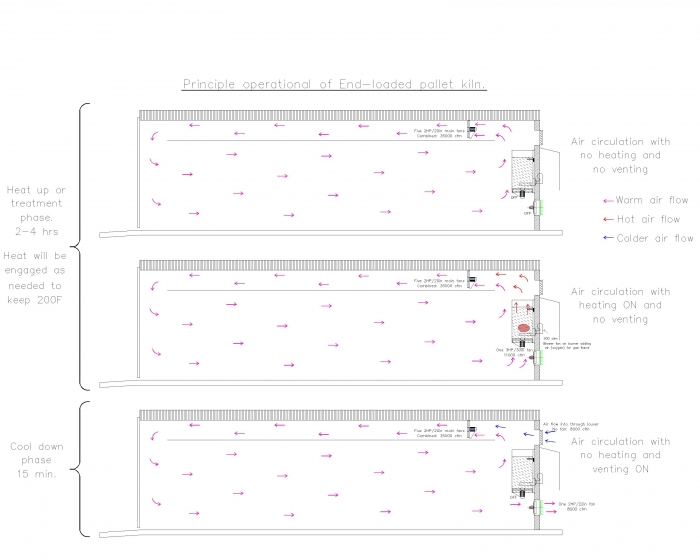 |
| SIDE FAN DESIGN |
|---|
Technically this should be as efficient as the standard kiln design unless the stacking width is to wide. We have only seen one manufacturer in the US with this design.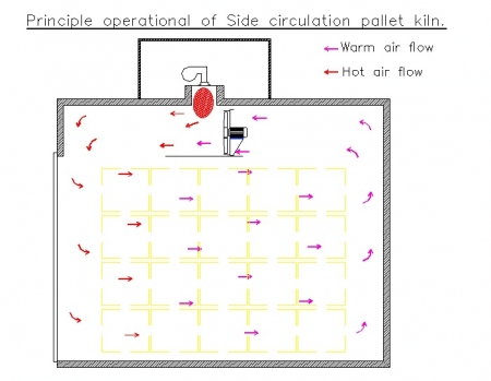 |
| LOW PUSH FAN DESIGN |
|---|
This often a compromised solution based on un-organized air circulation. This system is normally seen in HT systems that are installed in insulated containers / van-trailers. The only way we have found to compensate for the lack of organized airflow was to develop a portable fan header to help distribute the heat in the chamber as seen below. Without the portable fan header the HT cycle time will increase and therefore increase gas consumption.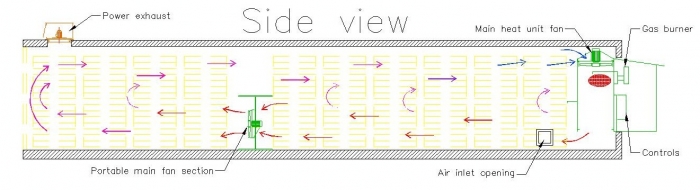 |
| HEAT CANNON DESIGN |
|---|
This is probably the most wasteful of all the HT chamber designs. Basically the hot air is not recycled to reduce the energy costs. This means that a lot of hot air is expelled from the chamber that should have been recycled. This was one of the first HT systems on the market and we rarely see these sold anymore.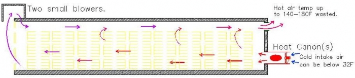 |
| CONTAINER BASED DESIGN |
|---|
| Why install pallet HT chambers into insulated containers / van-trailers? Because for most it makes a lot of sense at first thought. But in the end installing a pallet HT system in a container is a compromise to achieve the best combination of practical operation and adequate operation. Furthermore, an insulated container / van-trailer is unlikely to last as long as a real kiln solution. Four examples of container based designs and the compromises they had to make: 1. Heat cannon design Will load about 440-480 GMA pallets, but is the most wasteful system resulting in higher operating cost (=more gas cost) 2. Low push fan design Will load about 440-480 GMA pallets and it does recycle the hot air in the chamber, but the pallets furthest away from heat system above HT threshold will take longer. 3. Low push fan design + portable fan header Will load about 440-480 GMA pallets and it does recycle the hot air in the chamber and achieves reasonable heat distribution, which means that pallets furthest away from heat system will get above HT threshold faster than the other container based designs. 4. Standard kiln design (fan overhead) Will load about 340-400 GMA pallets and it uses the best design for heat treating; BUT with a lower loading height limits its practical application and we have not seen any sold in recent years. |
| OTHER DESIGNS |
|---|
|
Designs that do not seem to be available in the market any longer are listed below: |